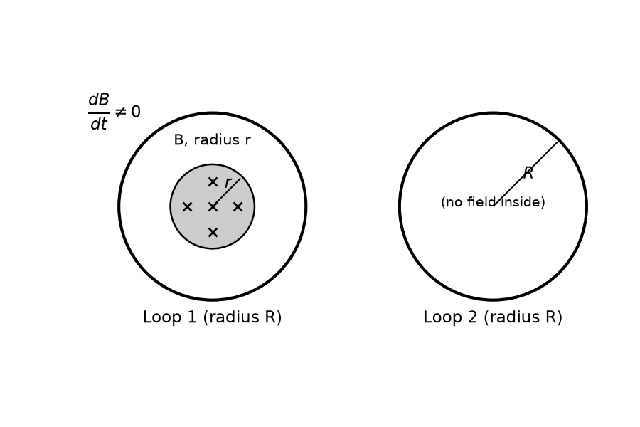
A uniform magnetic field is restricted within a region of radius r. The magnetic field changes with time at a rate dB/dt. Loop 1 of radius R > r encloses the region r and loop 2 of radius R is outside the region of magnetic field as shown in the figure below. Then the e.m.f. generated is
A long solenoid has 1000 turns. When a current of 4 A flows through it, the magnetic flux linked with each turn of the solenoid is 4 × 10⁻³ Wb. The self-inductance of the solenoid is:
A long solenoid of diameter 0.1 m has 2 × 10⁴ turns per meter. At the centre of the solenoid, a coil of 100 turns and radius 0.01 m is placed with its axis coinciding with the solenoid axis. The current in the solenoid reduces at a constant rate to 0 A from 4 A in 0.05 s. If the resistance of the coil is 10 π² ohm, the total charge flowing through the coil during this time is
The magnetic potential energy stored in a certain inductor is 25 mJ, when the current in the inductor is 60 mA. This inductor is of inductance
A cycle wheel of radius 0.5 m is rotated with constant angular velocity of 10 rad/s in a region of magnetic field of 0.1 T which is perpendicular to the plane of the wheel. The EMF generated between its centre and the rim is,
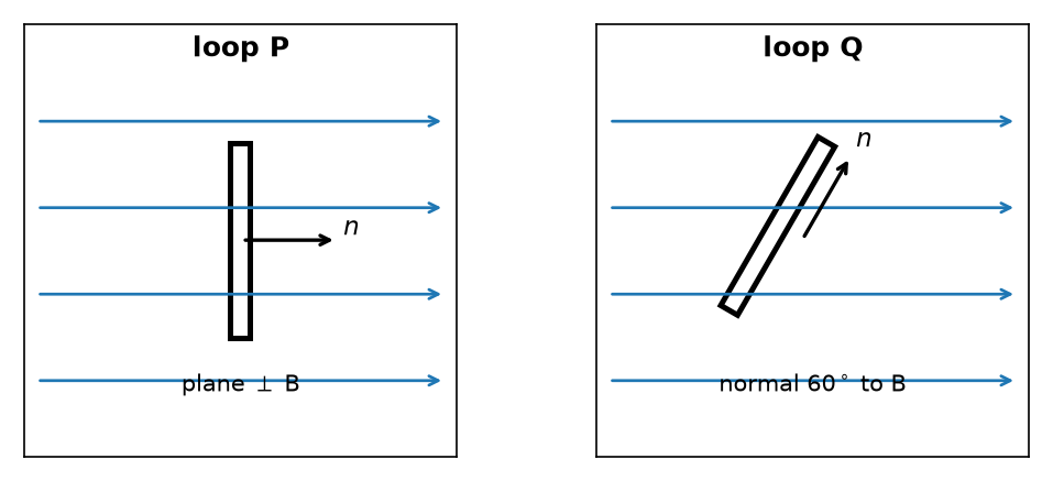
A 800 turn coil of effective area 0.05 m² is kept perpendicular to a magnetic field 5 × 10⁻⁵ T. When the plane of the coil is rotated by 90 degrees around any of its coplanar axis in 0.1 s, the emf induced in the coil will be:
Two ways to go deeper on this chapter
Choose your next step
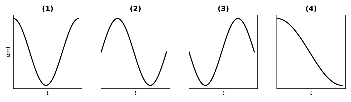
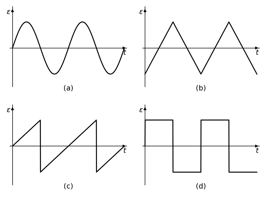
The variation of EMF with time for four types of generators are shown in the figures. Which amongst them can be called AC?
In which of the following devices, the eddy current effect is not used?
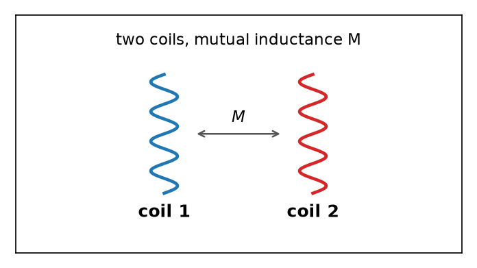
Two conducting circular loops of radii R1 and R2 are placed in the same plane with their centres coinciding. If R1 >> R2, the mutual inductance M between them will be directly proportional to:
A square loop of side 1 m and resistance 1 Ω is placed in a magnetic field of 0.5 T. If the plane of loop is perpendicular to the direction of magnetic field, the magnetic flux through the loop is
A big circular coil of 1000 turns and average radius 10 m is rotating about its horizontal diameter at 2 rad s⁻¹. If the vertical component of earth's magnetic field at that place is 2 × 10⁻⁵ T and electrical resistance of the coil is 12.56 Ω, then the maximum induced current in the coil will be:
An emf is generated by an ac generator having 100 turn coil, of loop area 1 m². The coil rotates at a speed of one revolution per second and placed in a uniform magnetic field of 0.05 T perpendicular to the axis of rotation of the coil. The maximum value of emf is:
The magnetic energy stored in an inductor of inductance 4 µH carrying a current of 2 A is:
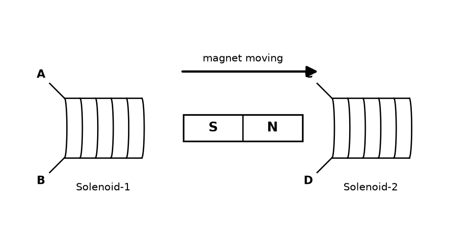
In the above diagram, 1 strong bar magnet is moving towards solenoid - 2 from solenoid - 1. The direction of induced current in solenoid - 1 and that in solenoid - 2, respectively, are through the directions:
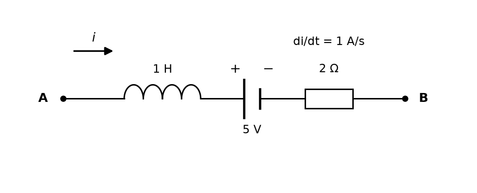
AB is a part of an electrical circuit (see figure). The branch contains an inductor of 1 H, a 5 V battery, and a 2 ohm resistor in series between A and B. The potential difference "V_A - V_B", at the instant when current i = 2 A and is increasing at a rate of 1 amp/second is:
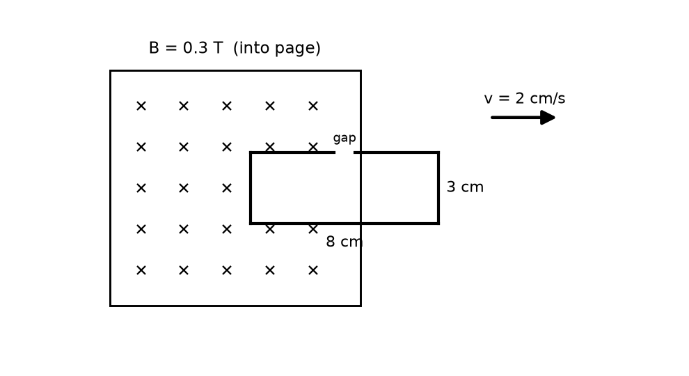
A rectangular wire loop of sides 8 cm and 3 cm with a small cut, is moving out of a region of uniform magnetic field of magnitude 0.3 T directed normal to the plane of the loop. The emf developed across the cut, if the velocity of the loop is 2 cm s⁻¹, in a direction normal to the shorter side of the loop, will be:
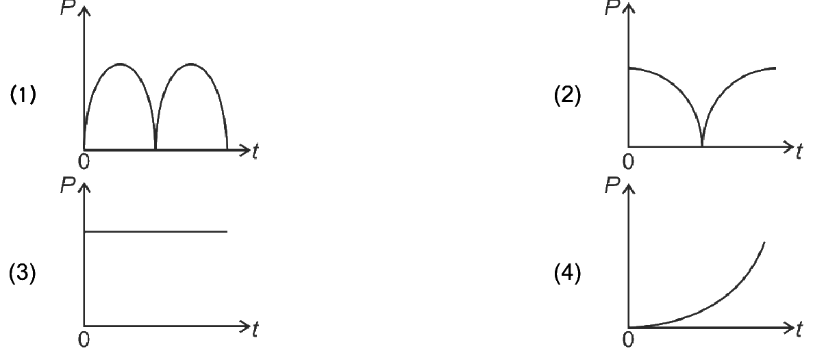
A conducting loop of finite resistance lies in the $x$–$y$ plane in a constant magnetic field along $z$. The area of the loop varies with time as $A=A_0(1+\sin t)$. The figure that correctly indicates the qualitative behaviour of the power $P$ dissipated in the loop as a function of time is:
Consider a long solenoid of length $l$ and radius $r$. If $n$ is the number of turns per unit length and $\mu_0$ the permeability of free space, the inductance of the solenoid is:
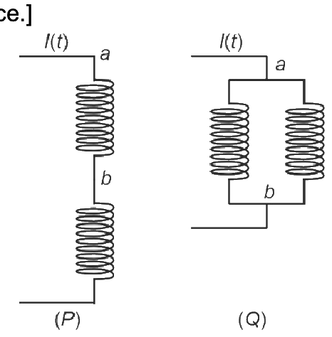
Two identical inductors are connected in two different configurations $P$ (series) and $Q$ (parallel), where a time-varying current $I(t)$ flows, as shown. The induced emf between points $a$ and $b$ for configuration $P$ is $E_P$ and for $Q$ is $E_Q$. The ratio $E_P/E_Q$ is: [Neglect mutual inductance.]
Want more Electromagnetic Induction questions?
MedicNEET has 43,000+ NEET-style questions across Physics, Chemistry & Biology with detailed NCERT-based explanations — including the long, tricky questions that actually come in the exam.
Download MedicNEET App — Free